How to Select Test Equipment According to the RTCA DO-160G Standard
7.1 Purpose of the Tests
The operational shock test verifies that the equipment will continue to function within performance standards after exposure to shocks experienced during normal aircraft operations. These shocks may occur during taxiing, landing or when the aircraft encounters sudden gusts in flight. This test applies to all equipment installed on fixed-wing aircraft and helicopters. Two operational shock test curves are provided, a standard 11 ms pulse and a low frequency 20 ms pulse. The 20 ms pulse may not be adequate to test against the effect of longer duration shocks on equipment that have its lowest resonance frequency (as per section 8) below 100Hz. For such equipment, a pulse of 100 ms duration should be considered.
The crash safety test verifies that certain equipment will not detach from its mountings or separate in a manner that presents a hazard during an emergency landing. It applies to equipment installed in compartments and other areas of the aircraft where equipment detached during emergency landing could present a hazard to occupants, fuel systems or emergency evacuation equipment. These tests do not satisfy FAR requirements for all equipment, e.g. seats and seat restraints.
Note: For fixed-wing aircraft: a complete installation demonstration, i.e. including aircraft acceleration loads (such as flight maneuvering, gust and landing) in addition to the crash safety loads, may be accomplished by using the "Unknown or Random" orientations for the "sustained" test procedure.
Using a dummy load on the shock test apparatus may be necessary to ensure that the recorded shock pulse will be within the specified tolerances of Figure 7-2.
7.1.1 Equipment Categories
Category A
Equipment tested for standard operational shocks.
Category B
Equipment tested for standard operational shock and crash safety.
Category D
Equipment tested for low-frequency operational shock.
Category E
Equipment tested for low-frequency operational shock and low frequency crash safety.
7.2 Operational Shocks
Performance compliance requirements are normally required following application of the shocks. If equipment requires monitoring during the application of the shock pulses, the monitoring requirements must be stated in the relevant equipment specification.
7.2.1 Test Procedure
Secure the equipment to a shock table by means of a rigid test fixture and mounting means intended for use in service installations. The mounting of the equipment should include those non-structural connections that are a normal part of the installation. The accelerometer used to measure or control the input shock pulse shall be placed as close as practicable to an equipment attachment point. The test system accuracy to measure acceleration shall be within ±10 percent of standard reading. Unless otherwise stated in the EUT specification, the equipment shall be operating, and its temperature stabilized. Apply to the test item three shocks having a terminal saw-tooth wave shape with an acceleration peak value of six (6) g's in each orientation. The nominal pulse duration shall be 11 ms for standard shock testing and 20 ms for low frequency shock testing. The characteristics of instrumentation used to demonstrate compliance and the shock pulse tolerance limits are shown in Figures 7-1 and 7-2, respectively. An equivalent shock response spectrum may replace the terminal saw-tooth wave shape.
After application of the shocks, DETERMINE COMPLIANCE WITH APPLICABLE EQUIPMENT PERFORMANCE STANDARDS.
When using a conventional drop shock machine, the equipment shall be shock tested in the following orientations:
a. Normal upright.
b. Suspended upside down.
c. At orientations such that the first major orthogonal axis of the equipment successively forms angles of +90 degrees and -90 degrees (two orientations) with the plane of the table.
d. At orientations such that the second major orthogonal axis of the equipment successively forms angles of +90 degrees and -90 degrees (two orientations) with the plane of the table.
7.2.2 Alternate Test Procedure
It is permissible to apply the shocks specified in paragraph 7.2.1 with the equipment mounted in its normal operating orientation (i.e., as spatially oriented in its customary aircraft installation), provided that three shocks are applied in both directions of the three orthogonal axes.
7.3 Crash Safety
If the crash safety test is applicable, both the impulse and sustained test procedures shall be performed.
During the impulse tests of paragraphs 7.3.1, 7.3.2 or 7.3.3, an equivalent weight (dummy load) may be substituted for electrical-mechanical components normally mounted within or on the equipment case. Such equivalent weight shall approximate the weight of the components that it replaces and shall be so located that the center of gravity of the equipment is essentially unchanged. The equivalent weight shall not contribute to the strength of the equipment case or its mounting fastenings to a greater extent than the components it replaces.
7.3.1 Test Procedure 1 (Impulse)
Secure the equipment or dummy load to a shock table by means of a rigid test fixture and mounting means intended for use in service installations.
In each of the six equipment orientations listed in paragraph 7.2.1, apply one 20 g shock having a wave shape identical to that specified in Figures 7-1 and 7-2. After application of the six shocks, bending and distortion shall be permitted. There shall be no failure of the mounting attachment and the equipment or dummy load shall remain in place.
7.3.2 Alternate Test Procedure (Impulse)
It is permissible to apply the shocks specified in paragraph 7.3.1 with the equipment mounted in its normal operating orientation provided that these shocks are applied in both directions of the three (3) orthogonal axes.
7.3.3 Test Procedure 2 (Sustained)
It is expected that the sustained test procedure below will normally be carried out using a centrifuge or sled. In certain cases, however, it is acceptable to simulate the effects of inertia by applying forces statically through the center of gravity of the equipment under test, providing it can be determined that other parts within the equipment can be contained within the casing of the equipment should they break loose.
Secure the equipment or dummy load to test facility by means of a rigid test fixture and mounting means intended for use in service installation. Apply the appropriate test loads for a minimum of three seconds in each direction of load. "Direction of load" in Table 7-1 applies to the aircraft's major orthogonal axes. The applicable test levels are given in Table 7-1 (*). Where the orientation of the equipment to the aircraft axes is known, then the required load and direction of load relative to the equipment can be determined. The airplane directions together with the definitions regarding a centrifuge test are provided on Figure 7-3. If the orientation of the equipment under test is unknown or not fixed in relation to the aircraft axes, then the random orientation is required along each direction of the equipment's three orthogonal axes as defined in Table 7-1. After application of the six loads, bending and distortion shall be permitted. There shall be no failure of the mounting attachment and the equipment or dummy load shall remain in place.
The crash safety load requirements represent inertia load requirements, with the loads being in the same direction as the g’s. If a static test were used to demonstrate compliance, the load would be applied in the same direction as the g requirement. If a centrifuge is used, the loads are opposite the direction of the acceleration. In order to simulate the inertia loads doing a centrifuge test, the equipment must be oriented such that the loads are in the correct direction, not the acceleration. For instance, for a 9 g Forward test, the front end of the equipment shall face opposite the center of the centrifuge. That would simulate the inertia loads the equipment would see for the Forward 9g condition.


Recommended equipment
KRD11/KRD12 Pneumatic Shock Test System

KRD14/15 Pneumatic Shock Response Spectrum Test System
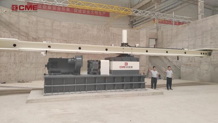
KRD31 Constant Acceleration Tester (Arm Type)