How to Select Test Equipment Based on MIL-STD-202H Standard - Acceleration Test
MIL-STD-202H
This standard establishes uniform test methods for electronic and electrical components, including basic environmental tests to determine their ability to withstand the harmful effects of natural elements and surrounding conditions under military operational environments, as well as physical and electrical performance tests. In this standard, the term "component" includes capacitors, resistors, switches, relays, transformers, inductors, and other similar devices. Unless otherwise specified, this standard applies only to small components weighing no more than 300 pounds or with a test voltage RMS not exceeding 50,000V.
1. Method 212: Acceleration Test
Purpose: This test is designed to determine the effects of acceleration stress on component parts and to verify that these components can operate properly when subjected to acceleration stresses similar to those encountered in environments such as aircraft and missiles.
Test Conditions
Test Condition A
Test specimens shall be subjected to a steady-state acceleration test for 5 minutes in each of the six directions along three mutually perpendicular axes, for a total test duration of 30 minutes. The acceleration magnitudes shall be 20g, 50g, and 100g. The acceleration magnitude at any point on the test specimen shall not exceed the specified value by more than 15%.
Test Condition B
Test specimens shall be subjected to a steady-state acceleration test for 1 minute in the directions specified by the relevant standard. The acceleration magnitudes shall be 10,000g and 20,000g. Acceleration shall be smoothly increased from zero to the specified value over a period of no less than 20 seconds, and smoothly decreased from the specified value to zero over a period of no less than 20 seconds.
Test Condition C
Test specimens shall be subjected to a steady-state acceleration test for 10 minutes in each of the six directions along three mutually perpendicular axes, for a total test duration of 60 minutes. The acceleration magnitude shall be specified by the relevant standard. Acceleration shall be smoothly increased from zero to the specified value over approximately 2 minutes, and smoothly decreased from the specified value to zero over a period of no less than 2 minutes.
Test Equipment:
Unless otherwise specified, acceleration test equipment shall be of the centrifuge type and capable of subjecting the test specimen to the specified acceleration values. The acceleration gradient across the test specimen shall not exceed 15% of the specified g level.
Test Specimen Mounting:
Unless otherwise specified, provisions shall be made to allow mounting by normal means so that the test specimen can be tested in each of two directions (180 degrees apart) for each of three mutually perpendicular axes. Components with axial leads weighing less than 0.5 ounces (approximately 14.2 grams) shall be soldered to upright terminals, with the distance from the component lead-out point to the terminal kept between 0.2 inches and 0.3 inches (approximately 5.1 mm to 7.6 mm). Components weighing 0.5 ounces or more shall be clamped to avoid inducing any stress on the leads. Components with radial leads and components with special mass distributions shall be mounted as specified in the individual specification. If load current, excitation current, or polarization current needs to be applied, it shall be specified. Every precaution shall be taken to ensure that all electrical connections are secure and reliable.
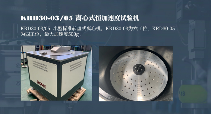
2. KRD30 Constant Acceleration Tester (Arm Type)
Equipment Introduction


The KRD30 series centrifuge tester is a multi-station turntable-type centrifuge used to determine the structural adaptability and performance of electronic components, small assemblies, and other electrotechnical products under the forces generated by steady-state acceleration (constant acceleration) environments, such as those produced by moving vehicles, airborne vehicles, rotating machinery, and projectiles. It is also used to assess the structural integrity of some components. It can also be used to determine the effects of constant acceleration on electronic devices, with the purpose of revealing structural and mechanical defects that may not necessarily be detected during shock and vibration tests. It can also be used as an overstress test to determine the structural strength limits of packaging, internal metallization and lead systems, chip or substrate adhesion capabilities, and other structural components of electronic devices. If appropriate stress levels are determined, this test can also be used as a 100% screening test on the production line to detect and reject any device whose structural component mechanical strength is below the nominal value.
Technical Specifications

Functional Features
- Advanced Control System: Fully automatic computer remote real-time control interface. The operator only needs to input simple values to start the equipment and accurately complete the acceleration test.
- User-friendly Display Interface: The control interface can display test curves, tolerances, and test time in real time.
- Powerful Multi-acceleration Continuous Testing System: Enables multi-level acceleration continuous testing according to the different requirements of the test samples.
- Reliable Protection Measures: Provides circuit break, over-limit, and overspeed protection.
- Multiple Control Modes: In case automatic control fails or is not required, the device can still complete the test using manual control.
- Convenient and Efficient Result Output System: After the test is completed, a test report is automatically generated and printed.
Equipment Video

3. KRD31 Constant Acceleration Tester (Arm Type)


The KRD31 series rotary arm type constant acceleration centrifuge tester is used to determine the structural adaptability and performance of electronic components, small devices, and other electrotechnical products under the forces generated by constant acceleration environments (excluding gravity), such as those produced by moving vehicles, airborne vehicles, rotating machinery, and projectiles. It is also used to assess the structural integrity of some components.
This equipment mainly consists of a conductive slip ring assembly, a rotary arm assembly, a transmission system, a chamber and base, an AC measurement and control system, a monitoring system, and an interlock safety system. The three-phase AC motor drives a pair of spiral bevel gears for deceleration via an elastic pin coupling. The large bevel gear is mounted on the rotating main shaft, and the working arm is also fixedly connected to the rotating main shaft, thus driving the working arm to rotate around the main shaft. The test sample is mounted on the arm mounting surface at a specified radius from the rotating main shaft. When the arm rotates at a constant speed around the main shaft, the test sample on the arm is subjected to a centrifugal constant acceleration. By changing the mounting radius of the test sample and the rotational speed of the arm, the desired acceleration value can be obtained.
The safety of the rotary arm centrifuge is of paramount importance. Therefore, during equipment installation, the centrifuge should be installed in a test pit.
Technical Specifications